Spotlight on DALI
With the market for smart lighting and connected controls projected to continue to grow for the foreseeable future, Mike Collins, Managing Director at Ovia – part of the Scolmore Group of companies, answers some questions on the DALI protocol, described as the largest wired digital open protocol in the world for lighting.
Originating in the late 1990s, DALI (Digital Addressable Lighting Interface) is a bi-directional communications protocol that is used to provide control over, and communication between, the components in a lighting system.
Key features of DALI:
- It is an open protocol – any manufacturer can use it
- With DALI-2, interoperability between manufacturers is guaranteed by mandatory certification procedures
- Installation is simple; power and control lines can be laid together and no shielding is required
- The wiring topology can be in the form of a star (hub & spoke), a tree or a line, or any combination of these
- Communication is digital, not analogue, so the exact same dimming values can be received by multiple devices resulting in very stable and precise dimming performance
- All devices have their own unique address in the system opening a very wide range of possibilities for flexible control. This also allows all devices to be individually monitored and maintained
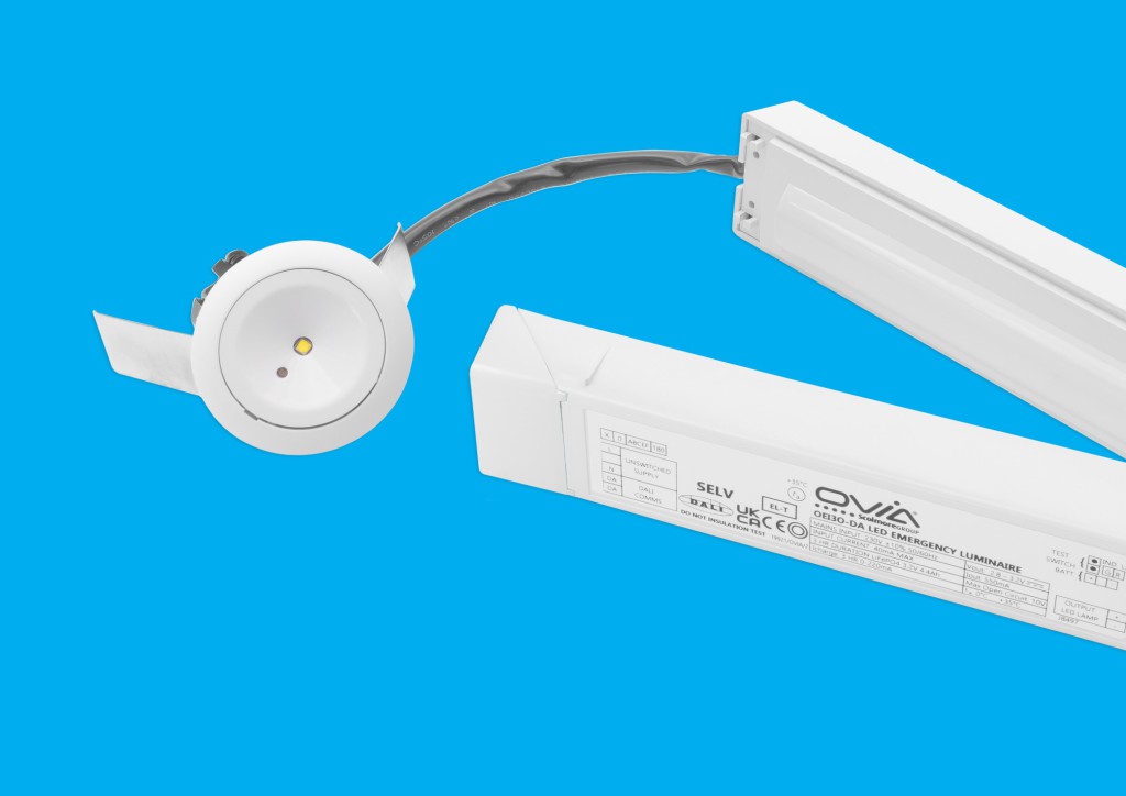
The latest addition to Ovia’s extensive lighting solutions range is the Pin Spot DALI – a range of LED DALI emergency conversion modules with self-test that can be integrated into any DALI addressable install.
How does DALI compare with 1-10V?
DALI, like 1-10V, was designed for and by the lighting industry. Lighting control components, such as LED drivers and sensors, are available from a range of manufacturers that have DALI and 1-10V interfaces. However, that’s where the similarity ends.
The main differences between DALI and 1-10V are:
• DALI is addressable. This opens the way for many valuable features such as grouping, scene-setting and dynamic control, such as changing which sensors and switches control which light fittings in response to office layout changes.

• DALI is digital, not analogue. This means that DALI can offer much more precise light level control and more consistent dimming.
• DALI is a standard, so, for example, the dimming curve is standardised meaning that equipment is interoperable between manufacturers. The 1-10V dimming curve has never been standardised, so using different brands of drivers on the same dimming channel could produce some very inconsistent results.
• 1-10V can switch a luminaire off/ on only having the function to dim between 10 – 100%. DALI can dim between 0 – 100%, manage colour control, carry out scheduled emergency lighting tests logging the data, also logging other data such as energy usage and status. DALI can also carry out complex scene-setting and many other lighting-specific functions.
How does DALI work?
The core of DALI is a bus – a pair of wires that carries digital control signals from input devices (such as sensors) to an application controller. The application controller applies the rules with which it has been programmed to generate outgoing signals to devices such as LED drivers. You can have up to 64 addresses on a single DALI line with multiple lines on any system. A DALI line can vary in length – if using a 1.5mm cable, a length of up to 300m can be installed.
Bus power supply unit (PSU). This component is always required. It maintains the bus voltage at the required level.
LED fittings. All light fittings in a DALI installation require a DALI driver. A DALI driver can accept DALI commands directly from the DALI bus and respond accordingly. The drivers can be DALI or DALI-2 devices, but if they are not DALI-2 they will not have any of the new features introduced with this latest version, such as querying control gear failure, resending failed commands, or identifying devices.
Input devices – sensors, switches etc. These communicate with the application controller using 24-bit data frames. They do not communicate directly with the control devices (DALI 2 only).
Instances. Often, a DALI device such as a sensor will offer several different instructions to the DALI system. For example, sensors often include a movement detector (PIR), a light-level detector and an infrared receiver. These are called instances – the single device has three instances. With DALI-2 each instance can belong to a different control group, and each can be addressed to control different lighting groups giving great flexibility.
Control devices – application controller. The application controller is the ‘brains’ of the system. It receives 24-bit messages from the sensors (etc) and issues 16-bit commands to the control gear. The application controller also manages the data traffic on the DALI bus, checking for collisions and re-issuing commands as necessary.
As a business, Ovia is continually developing products that incorporate the latest technology and our list of fittings that are compatible with the DALI protocol continues to be expanded.